C R G CRG Reports Exterior Engine 1967 Model ID
Numbers Decode General Info Interior Transmission 1968 Model ID
Drivetrain Decode Options Underhood Chassis 1969 Model ID

CRG Research Report

Delco-Remy Transistor Ignition Systems as Used on the Early Camaro
A Comprehensive Primer to the Forgotten DelcotronicTransistor-Controlled
Magnetic-Pulse-Type Ignition System

© 2003-2014, Thomas M. Bogan and Camaro Research Group

Contributing Author -
Reviewed by the CRG
Last Edit: 26-Nov-2013
Previous Edits: 28-Jun-2003
Original Release: 28-Jun-2003

Index

Note: Prior to this, CRG Research Reports had only been written by CRG members. While Dr. Bogan is not a CRG member, his offer to have CRG publish this significant research contribution merits highlighting the work as a CRG Research Report. CRG thanks Dr. Bogan for his work as a contributing author to the CRG!  

History of the TI System

The "Delcotronic Transistor Controlled Magnetic Pulse Type Ignition System" is seldom, if ever, seen or discussed, but it was a key part of Chevrolet's racing success during the late 1960's and early 1970's. This special transistor controlled ignition system was developed for high performance and racing use to replace the traditional point-fired ignition system found on regular production vehicles. This first electronic ignition, known by such names as Magnetic Impulse, Mag-Pulse, Transistor Ignition, or simply TI, became the standard in heavy-duty high performance Chevrolet ignition systems. With the development of newer technology such as capacitive discharge, multiple spark, and multi-coil systems, these early milestones of Chevrolet racing history have almost been forgotten. Up until the development of the MSD ignition systems in the mid-1970's, you'd be hard pressed to find a better ignition system for your race or high performance Chevrolet. These systems earned the praises of racers because they solved many of the problems inherent to the point ignition systems.

Point triggered ignition systems can bounce (limiting rev capability) unless they have very high tension point sets. These high tension points are fine for short distance racing. However, when high tension points are used in an endurance racing event such as Trans Am or NASCAR, the rubbing block wears at a fast rate. This results in increased dwell angle, retarded spark timing and eventual complete ignition failure. The problem is critical in endurance events where the engine is expected to run at high RPM for an extended period of time. The TI system solved these problems and was reliable up to 10,000 RPM all day long. Instead of using a point set to make and break electrical contact to the coil, the TI uses a magnetic pickup and transistors to interrupt the coil current and fire the spark plug. Racers quickly made these the "standard" in racing ignition systems for Chevrolet and Pontiac engines. In their day, TI systems had widespread use in many racing series such as Trans Am, Can Am, road racing, NASCAR, drag racing, and others. Many races and championships were won with TI systems.

Delco-Remy first developed their new transistor controlled ignition system for the full-size Pontiac 389 and 421 engines on 1963 models. Throughout the 1960's, various cars could be ordered with a TI system including Corvettes, full-size Chevrolets (including the 409), Chevelles, Chevy II's, and eventually as an over-the-counter (OTC) setup to install on any Chevrolet small or big block engine. The 1969 aluminum block ZL1 was the only Camaro that came with a factory installed TI system.

When the Camaro debuted in the fall of 1966, several racing series were underway and growing in popularity. To help bolster its performance image and sales, Chevrolet wanted to prove their new car in competition, especially in the SCCA's Trans Am series. To do this they created a new Camaro model that would be known as RPO Z28. By destroking the 327ci engine with a heavy-duty version of the 3-inch stroke crankshaft from the 283ci engine, the now-famous 302ci Z28 engine was created, which just met the SCCA five-litre engine displacement limit. This special high-revving engine had several high performance components that helped it to develop considerably more output than the advertised 290 HP. The first run of RPO Z28 Camaros was built in late December 1966/early January 1967 for the fast-approaching Trans Am racing season, which would start with Daytona in early February. The majority of these were intended primarily for racers and delivered to select dealers to be setup as race cars.

Chevrolet wanted to be competitive quickly and put their Engineering, Research & Development, and Product Performance Liaison groups to work developing racing components for the Camaro. At the time, official Chevrolet Corporate policy was that they were not involved in racing or sponsorship of any racing activity. However, behind closed doors, these departments were very busy developing parts aimed at making the Camaro a successful racer. The competition parts were available initially only to those that Chevrolet selected. Eventually these special parts became known and available to the racing public to satisfy the SCCA and other sanctioning bodies.

Chevrolet did publish this information. First, you had to know that this information even existed. If you could then write a convincing letter, Chevrolet Engineering would send a special set of four photocopied pamphlets out to you in a plain envelope. The "Camaro Z-28 Heavy Duty Parts" and "302-327-350 Heavy Duty Parts" lists catalogued competition parts that were not listed in the regular parts book. The "Camaro Chassis Preparation" sheets were special instructions available for setting up a Camaro chassis for Trans Am racing use and "Clearance and Specifications for Heavy Duty Service 302 CU. IN. Chevrolet Engine" sheets were instructions on how to setup the engine. These sheets evolved into the Chevrolet Special Equipment manual, (also known as the Green Sheets) which in the early 1970's then became the Chevrolet Power Manual. Both Paul Van Valkenburgh's book Chevrolet = Racing? and Mark Donohue's book The Unfair Advantage are highly recommended reads and discuss different aspects of Chevrolet's clandestine involvement in racing.

The world would soon find out that the Z28 was a serious contender at the racetrack. And the Camaro would soon be a very popular vehicle on the dealership sales lots as well. In their first year of competition in 1967, the Z28 Camaros performed well in drag racing, but started very slowly in their intended target - road racing - because it took longer than anticipated to resolve rear suspension and brake problems. But the suspension and brakes were sorted out with great success by the end of the 1967 Trans Am racing season, and though the Z28 did not win the overall championship in 1967, it did finish its first season on a high note with a string of victories. The Z28 went on to dominate Trans Am racing in 1968 and 1969 as the Roger Penske and Mark Donohue Sunoco Camaros had incredible success, winning the championship both years.

Many of the components that were developed for the Camaro racing programs were actually borrowed from other existing lines such as: Corvette disc brakes, Cross-Ram intake manifold from the Mark IV engine program, and the cowl plenum induction from the 409. The Transistorized Ignition is yet another example of this. A new TI distributor, PN 1111267, was made with an advance curve specifically tailored for the 302 engine. A special amplifier mounting plate, PN 3916730, was made. And the bulk of the remaining components were borrowed from existing applications: The main harness PN 2988218 from the full-size Chevrolet, along with PN 6287841 starter extension harness, the existing ignition amplifier PN 1115005, the existing TI coil PN 1115207, and the PN 2987102 ignition switch power feed extension from the 1966 Nova. These parts along with some miscellaneous items (wiring connector, ties, grommet, instruction sheets) comprised the first Transistor Ignition systems for the new Camaro. It was only available as an over-the-counter (OTC) service part.

Coincidentally, with the introduction of the Camaro in 1966, the Delco-Remy TI system was undergoing several revisions. Because of this, several design changes took place that added confusion about these systems. The very limited production of these parts furthered the confusion. It is hoped that this article can clarify how the TI systems were used on the early Camaro. A convenient summary table is included to help the reader in understanding how they were setup. It is hoped this will aid anyone considering one of these systems for use on their Camaro.

System Components

A Transistor Ignition system consists of the following components:

  1. Special magnetic pulse distributor
  2. Ignition pulse amplifier
  3. Mounting plate for amplifier
  4. Special TI Coil
  5. Wiring harness assemblies
  6. Miscellaneous parts (retainers, grommet, wiring connector, instruction sheets)

All parts were available separately. For convenience, a kit was available that included all necessary items, less the distributor. This kit was called a Transistorized Ignition Unit (TIU). These TIU's helped prevent a lot of headaches when setting a system up. Most original systems were setup with a TIU. Today most are setup by pieces. The following sections will look at each of these TI components separately and discuss the changes that were made over the years.  

Magnetic Pulse Distributors

The initial offering for the TI distributor on Camaros was PN 1111267 for the 1967 Z28. Essentially it was a regular iron-housing, mechanical-tach-drive, TI distributor with an appropriate advance curve to suit the 302 CI engine. The specifications were 14 degrees maximum mechanical advance at 2300 RPM (distributor degrees and RPM). It had a vacuum advance feature that most racers did not utilize. The 267 distributor was one of the distributors recommended in the Heavy Duty Parts listings and Chassis Preparation Sheets and was available from November of 1966 up to the mid-80's.

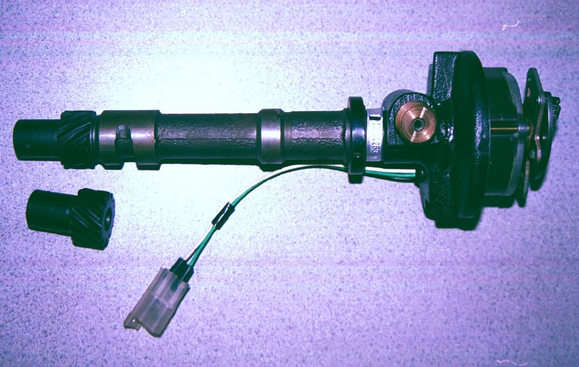
TI ball bearing distributor PN 1111263.
(Note the incomplete oil groove and compare drive gear to the standard drive gear on left.)
Ball Bearing Distributor 1111263

An alternative distributor was also listed. This is the highly prized ball bearing distributor PN 1111263. This heavy-duty version was initially released for the reverse-drive camshaft 427 big block racing engine. It has a special ball bearing on the upper part of the mainshaft instead of the usual bronze bushing. This distributor has an iron housing with a mechanical tach drive and has a special reverse-drive distributor gear that permitted clockwise rotation of the distributor in this special 427 engine. It specified 13 degrees maximum mechanical advance at 1900 RPM. This distributor did not have a vacuum advance feature; the plate inside the distributor was fixed in position. (This distributor was still listed in the 1991 Chevrolet parts books, for $1,699.05!)

The 263 distributor required two changes for use in the small block 302 engine. First, the provided drive gear was replaced with the standard drive gear. And second, the lower oiling channel on the lowest boss was extended full circumference. (As supplied by Chevrolet, the lower oiling channel traversed only 3/4 of the circumference; if not fully grooved - like the standard small-block distributor - the oil passage that feeds the right-side camshaft lifter bank could be blocked, resulting in immediate engine failure!) In addition, it was often desirable to revise the provided advance curve to better match a given application. (Most racers changed the advance curve anyway.)

The 263 ball-bearing distributor had an advantage when the Cross-Ram dual 4-barrel setup became available for the 1968 Trans Am racing season. Because the 263 didn't have a vacuum advance unit it was easier to clear the number eight runner on the Cross-Ram manifold. The distributor tach drive could be moved around to suit the application. The previously mentioned 267 distributor can also be used, but it is a much more difficult fit in the Cross-Ram manifold application.

A third TI distributor for OTC TI applications was PN 1111095. This was a ball-bearing distributor similar to the 263, but without a tach drive.

ZL1 TI distributor PN 1111927.
(Note the vacuum advance unit and brown cap.)
ZL1 Distributor 1111927

The fourth TI distributor is the one that came from the factory on the sixty-nine 1969 ZL1 cars. These were the only Delco-Remy Transistorized Ignition systems that were factory installed on the early Camaros. This distributor is PN 1111927. This distributor has an iron housing with a mechanical tach drive and it was provided with 14.5 degrees maximum mechanical advance at 2500 RPM. The distributor had a dummy vacuum advance without a hose attachment that served to fix the advance plate into position in the distributor and a plastic cover over the tach drive hole.

As yet another option, parts were also available to convert a standard aluminum distributor to a TI magnetic pick-up distributor.

It was possible to use any of these distributors (or a TI distributor from other Chevrolet models, e.g. Corvette, Chevelle, etc) on other Camaro applications; they were not necessarily limited to use on the 302 Z28 or 427 ZL1.  

Ignition Pulse Amplifiers

The Delco-Remy ignition pulse amplifier for the transitor ignition were built with germanium-type transistors, which were the best available at the time the TI systems were developed. However, germanium transistors have a notable problem with heat sensitivity. Some reports indicate 140 degrees Fahrenheit is enough to damage them. Being at least somewhat aware of the issue, Chevrolet specified that the amplifier be mounted (more below) on the hood latch support brace in order to receive maximum benefit of cooling air. This helped avoid heat related failure. The author still uses his original circuit board and has had no troubles - but he carries a spare wherever he goes! (This heat problem has been addressed in the modern silicon transitor replacement circuit board assemblies that are available from M&H Electrical Fabricators, Inc. and several restoration parts suppliers (see the resources listing at the bottom of article). The silicon-based replacements are inherently much less heat sensitive than the originals.)

OTC TI Amplifier PN 1115005.
(Note plug-in connector.)
Plug-In Amplifier 1115005

The amplifier that Chevrolet originally specified for use in OTC systems was PN 1115005; this part has the plug-in socket style connector. Chevrolet identified a moisture intrusion problem with the 1115005 amplifier in other vehicles in their Service News publication dated November 1966, just as the Camaro TI systems were coming out. The problem was aggravated by the mounting position in the grille. To correct the problem Chevrolet recommended drying the circuit board, then spraying it with lacquer or wire protective spray. They additionally recommended coating the cover gasket (old style gasket) with silicone grease, and putting additional grease between the cover and the base after reassembly. This attempt at a corrective action did not fully solve the moisture issue.

Delco-Remy separately sent out a service bulletin in April 1967 with corrective measures, and another revised bulletin in May 1968. The problem according to them was 1) moisture leakage past the back cover seal into the main housing and 2) moisture intrusion into the electrical connection at the plug.

To help correct the leakage problem, in January 1967 Delco-Remy released a re-designed cover plate and gasket. The original cover had a formed-in-place gasket; this new design cover had a separate rubber gasket. The first design cover is easily identified by its curved edges that somewhat "cupped" around the amplifier housing, while the re-designed plate was flat. The new cover PN 1960625 and gasket PN 1970226 were available as service parts from your Chevrolet or Delco-Remy part supplier. And to correct the electrical connector leak, Delco-Remy specified to pack the connector harness plug half-full with a special Dow Corning silicone grease. (Be aware that dielectric grease is a non-conductor of electricity and it can interfere with a good electrical connection.)

OTC TI Amplifier PN 1115343.
(Note pigtail-style connector cable.)
Pigtail-Style Amplifier 1115343

These continuing problems led Delco-Remy to redesign the amplifier, which they released in January 1968. Corvettes built after this date had the new PN 1115343 amplifiers for their TI systems (RPO K66). This new amplifier had a integrated "pigtail" wiring harness approximately 27 inches in length. It also incorporated the improved back cover plate and gasket. By using the 27-inch pigtail harness they were able to move the electrical connection away from the direct foul weather spray at the grille that plagued the first design amplifier. These two changes seemingly corrected the moisture contamination problems. (Note: The May 1968 Delco-Remy service bulletin further specified: "The assembly plant has been authorized to start packing the harness connector with silicone grease to effectively seal this area." This would pertain to the new 343 amplifier. They were still concerned that even the new design could have troubles!)

The circuit board inside the amplifiers on both PN 1115005 and PN 1115343 are the same. The only changes are the housing cover and the electrical connection. Many 343 amplifiers came with a special grounding clip that was attached with one of the back cover screws. The new 343 amplifier requires a different wiring harness (more about that later). The amplifiers have the appropriate identifying part number stamped on their housings. Many amplifiers had a date code stamped in ink on the back cover.

Ground Clip for 1115343 Amplifier.
Amplifier Ground Clip

One of the interesting things about the new 343 amplifier is that it was not listed in the Heavy Duty Parts lists until some time after May 1969. OTC TI systems apparently continued to come with the 005 amplifier despite the new 343 version being available. It is also interesting to note that all 1969 ZL1's that were built between late December 1968 and May 1969 came exclusively with 343 amplifiers. OTC systems had to wait for this upgrade!

When the new 343 amplifier came out, a replacement amplifier assembly kit became available for use on older PN 1115005 amplifier systems. This kit (PN 3955511) included the new 343 amplifier and a special adapter harness connector to use with the old 1115005-style harness. This kit was listed in the Heavy Duty Parts publications some time after May 1969.

Amplifier Mounting Plates

Chevrolet specified that the amplifier be mounted on a special plate that was attached to the hood latch support bracket. This would place the amplifier directly behind the grille to allow cool air to flow over it. The first amplifier mounting plate was PN 3916730, and was used on the OTC systems during 1967, 1968, and early 1969. (The May 1, 1969 Chevrolet Heavy Duty Parts list shows another number PN 3916739 for the 302, but this appears to be a typographical error.) The same publication shows another mounting plate, PN 3954206, for 302, 396 and 427 applications, perhaps intended to completely replace the earlier plate. The 1969 ZL1 used plate PN 3954206 exclusively. After 1969 the plate was dropped and, on later applications (1970 and up), the amplifier was mounted directly to the lower portion of the hood latch support brace.

It is not known how these part numbers may have differed. This seems to be an area of confusion and would be a good topic for further research.

Amplifier Mounting Position, Top View.
Amplifier Mounting Position, Top View
Amplifier Mounting Position, Closer View.
Amplifier Mounting Position, Closer View

Amplifier Mounting Position, Grille View.
(View as seen from exterior grille side.)
Amplifier Mounting Position, Grille-Side View
 

Transistor Ignition Coils

TI systems use a special ignition coil. These coils have lower impedance than the standard ignition coils and are capable of flowing much higher current. This allows them to make a hotter spark at high RPM ranges when the spark plug voltage requirement is higher. A standard coil is not able to generate sufficient secondary voltage to work properly in this application. Though there were several TI coil numbers, only two pertain to use on the Camaro. PN 1115207 ("207") was the coil used for all OTC systems and as the service replacement. PN 1115210 ("210") was the exclusive coil that came from the factory on the 1969 ZL1 Camaro and could not be purchased at the dealer as a service item.

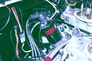
TI Coil Mounting.
(Shown here on a 1968 Cross-Ram intake car - note the special decal and harness connector.)
TI Coil As Seen on XRam Car

The TI coil differs in that the negative terminal is grounded directly to either (depending on the year and type of wiring harness) the firewall or the engine. In contrast, the standard ignition coil connects the negative terminal to the distributor wire and the electrical path passes through the points before going to ground. The TI coil receives 2.5-4.5 volts with the ignition switch turned on while the engine is off; in contrast, the standard coil operates at about 9 volts. Both coils receive 12 volts from the starter solenoid during starting.

Note that because the TI system creates the spark on the positive side of the coil (opposite from a points system, which generates the spark on the negative side), on an engine analyzer the graph or curve generated by TI has the opposite sign from that produced on a points ignition.

As mentioned, these Transistor Ignition coils have a lower impedance across the primary terminals. Standard coils measure 1.24- 1.46 Ohms. The TI coil measures 0.41-0.51 Ohms and most can be identified by a three-digit raised number, either 207 or 210, on the side of the case. These coils came with a special decal on the side indicating they were for the Transistor Ignition system. The first 207 coil was later replaced by a second version that had the full part number boldly stenciled in white on the side case (without any embossed numbers). A still later third version of the 207 coil made in Japan had a finely stenciled white part number and a different style coil wire tower, again without embossed numbers.  

Wiring Harness

The wiring harness is where things get very complicated. Confusion results primarily because of the amplifier change. If you remember that each amplifier had a different wiring harness system, it will be much easier to follow. Definitions of main and extension harness complicated matters as well. Keep these points in mind while reading through the next four subsections. Most of these harnesses are available in reproduction from either M&H Electrical Fabricators or Factory Fit (see the contact information at the end of the article).

Some of the very first Pontiac TI systems used two separate external resistors in the system. You may read about them in some early Transistor Ignition literature. Thankfully, these resistances were built into all Camaro Transistor Ignition wiring harnesses and you need not concern yourself about them.

1967-69 OTC Wiring Harness - a borrowed system

The first TI harness used on the Camaro for the 1967, 1968 and at least some of 1969 models was the PN 2988218 Ignition Pulse Amplifier Harness Assembly and the PN 6287841 Ignition Pulse Amplifier Extension Harness Assembly. These two harnesses comprise the "main harness" (as it would come to be known in later years). The 218 harness went from the amplifier in the grille to the firewall, via the lower left fender. The 841 harness is sometimes called the starter extension harness as it goes down to the starter solenoid (as well as to the distributor and coil). Both of these harnesses have a separate ground wire included into them. The 218 harness has a wire that grounds the amplifier to the radiator support. The 841 has a wire that grounds the coil negative terminal to the firewall.

Two Early OTC TI Harnesses.
(Early OTC harnesses: PN 2988218 on left,
PN 6287841 on right.)
Early OTC TI Harnesses

The third wire harness required on the 1967-68 setup is the PN 2987102 Ignition Switch to Ignition Pulse Amplifier Wire Assembly (WOW!). The 1969 OTC system may have used this harness as well. (Note: PNs 8901973 or 6297792 cannot be used in this application.) This short harness went from the 218 harness through the firewall to the ignition switch directly. The hole to be drilled in the firewall for this wire was specified to be 11/16-inch.

Other TI Wire Sets.
Other TI Wire Sets
From top to bottom:
Ground Wire
   PN 6297793
Starter Switch Extension Wires
   PN 8901973 (post 1969 OTC)
   PN 6297792 (ZL1)
   PN 2986913 (1968-69 OTC)
   PN 2987102 (1967-68 OTC)

Detailed instructions were provided on Chevrolet instruction sheet PN 3916731, released November 4, 1966. These instruction sheets were a part of the PN 3921048 Transistorized Ignition Unit.

May 1, 1969 Changes to OTC Harnesses

In the Chevrolet Heavy Duty Parts list dated 5/1/69, the OTC Ignition Impulse Amplifier Harness Assembly was changed to PN 6300109, which was listed for 302, 396 and 427 applications. Another Ignition Impulse Amplifier Extension Harness Assembly, PN 2988219, was added for 396 and 427 applications. The PN 6287841 starter extension harness listed above remained available and was now listed exclusively for the 302. A new Ignition Switch to Ignition Pulse Amplifier Wire Assembly, PN 2986913 was listed for the 396 and 427 applications. It is uncertain what ignition switch wire was specified for the 1969 302. It is likely that PN 2986913 was specified for all Camaro applications, replacing the earlier PN 2987102.

These harness changes continued to use the PN 1115005 amplifier unit, despite that the new PN 1115343 amplifier had been released (more that one year earlier!) on the Corvette. TIU 3921048 continued to be available.

The 1969 ZL1 Wiring Harness-getting simpler and better

The 1969 ZL1 Camaros were built between late-December 1968 and May of 1969.

These cars used an Ignition Pulse Amplifier Harness Assembly PN 6297791 (later revised in April 1969 to PN 6297688.) This harness was made to work with the new improved PN 1115343 pigtail amplifier. This single main harness replaced the two-piece main harnesses that were on the previous OTC systems. This new harness utilized the existing yellow wire from the starter solenoid, making it unnecessary to use the previous starter extension harness.

A special Ignition Pulse Amplifier Feed Wire Assembly, PN 6297792, connected to the ignition switch connector at the base of the steering column and provided the ignition switch power. The factory instruction manual specified a 3/4-inch hole be drilled through the firewall for this wire. The ground wire for the amplifier was dropped. Apparently the factory was satisfied that the housing had an adequate ground by its mounting method. The coil had a separate short ground wire, PN 6297793, from the negative terminal to the coil bracket mounting bolt. Details of this installation can be found in the 1969 Assembly Manual under COPO 9560.

Post May 1969 OTC Wiring Harness Systems - the simplest to set up

It is unclear exactly when, but sometime after midyear 1969, the OTC TI systems adopted the simplicity and improvements of the ZL1 TI setup. The change to the new main harness was made with the PN 6297688 Ignition Pulse Amplifier Harness Assembly. The PN 6297793 short coil ground wire was also used.

6297688 TI Main Harness.
6297688 TI Main Harness

A new Pulse Amplifier Ignition Feed Wire Assembly, PN 8901973, was released to connect to the fuse box wiring bulkhead connector in the engine compartment, after the coil positive wire was removed from it. This new generic wire allowed simple connection for all applications. It was no longer specified to drill a hole and connect to the ignition switch inside the car. The new 1115343 amplifier was used with this setup. The new amplifier will not connect to the previous 1115005-style harnesses. The instructions for setting up this version were in the Chevrolet Special Equipment manual (aka Green Sheets), which are currently being reproduced. Instructions can also be found on Chevrolet instruction sheets PN 3965743 which were dated November 16, 1970. This was the last harness available for use on the Camaro OTC systems. Note that this version continued to be available for the 1970-72 Camaros.  

Miscellaneous Parts

The miscellaneous pieces of the system (retainers, grommet, wiring connector, and instruction sheets) warrant some discussion.

The 1967-69 OTC system specified special ties to hold the wiring harness in place. These appear to be the same as the windshield washer hose loop through ties. Later versions, including the ZL1, specified the harness be taped in several locations.

The grommet was for either an 11/16-inch (early OTC) or 3/4-inch (1969 ZL1) hole drilled in the firewall to protect the ignition switch feed wire.

The electrical connector was used to (early) hook up the ignition feed wire to the ignition switch connector OR (later) to hook up the existing yellow starter solenoid wire to the main harness.

A special wiring harness clip, PN 3827371, was made to hold the amplifier harness to the hood latch plate. This is similar, but not identical to, the trunk light wire harness clip, as can be seen in the comparison below between between the 3827371 clip and the standard trunk light clip.

3827371 Wire Clip In Installed Position.
3827371 Wire Clip
Clip Comparison.
Clip Comparison

Following the appropriate instruction sheets during installation is highly recommended! Known instruction sheets in chronological order are: PN 3916731 dated 11-4-66, COPO 9560 ZL1 1969 Assembly Manual Instructions dated 12-16-68, PN 3965743 dated 11-16-70, and Chevrolet Special Equipment Green Sheets revised 3-9-72. It is possible other instructions sheets exist; if you have any not listed above, the author would like to hear from you.

Transistorized Ignition Unit Kit

The Transitorized Ignition Unit (TIU) kit saved the installer from numerous headaches, and included everything except the distributor. The content of these TIU's changed over the years because of the many revisions previously described, but it contained all of the correctly matched parts. It included the amplifier, ignition coil, wiring harnesses, mounting plate, grommet, electrical connectors, wiring straps, and instruction sheets.

TIU PN 3921048 was the first such TIU for the Camaro, and the instruction sheets were Camaro specific. It was used from its introduction March 7, 1967 through at least 1969. Again, the parts in the kit varied by the date at which it was purchased. The later Chevrolet Green Sheets list the Transistorized Ignition Unit PN 3997782 which included the parts needed to setup with the more weather resistant 343 amplifier. This was a more generic kit for any Chevy racing application.

The Tachometer Issue

Camaro TI distributors, like most others, came with a mechanical tachometer drive mechanism. It was speculated that the racer would use a mechanical tachometer. A mechanical tachometer can be setup but you may find it difficult to run the cable. The author has set one up successfully in a 1968 Camaro without butchering his vehicle, but it is challenging. You will find that your factory electronic tachometer will not read accurately if you try to drive it from the coil terminals (either + or - terminals). Apparently Stewart Warner used to make an adapter to drive their tachometers on a TI system. It is unknown if the adapter will drive a factory tach.

A special service bulletin from Delco-Remy for connecting a test tachometer to the system was released April 15, 1965. (Bulletin 1.2D-19). To use a tune-up tach, first locate the two-wire distributor connector. Find the side that the solid white wire is on. Connect your tachometer positive (+) lead to this point (easiest to attach on the other side of the distributors mating connector). The tachometer negative (-) lead should then be connected to the coil positive (+) terminal. (Yes - you read this right!) The author has successfully used a tune-up tach this way, but it seems to only work on tachs that have a separate power wire that attaches to the battery positive (+) terminal. Aftermarket performance tachometers (ones that don't have a separate 12-volt power wire) seem to not function when attached this way.

At least six of the sixty-nine ZL1's came with a factory tachometer. It is believed that they utilized standard production tachometers, but it is unclear how they addressed these issues.

However, we may be in luck as Mr. Dave Fiedler of T.I. Specialty is working on an electrical adapter to drive the factory tachometer. His company services, repairs and supplies parts for TI systems. He is extremely knowledgeable about TI systems and the author highly recommends him.  

Components Summary Table

Summarized in the following table are the components discussed in this article. This will help to clarify these TI systems and their components. The next time you are at a car show, you may want to look carefully to see if you can identify one of these obscure systems. They are quite a conversation piece and an asset to the value of any car. Be prepared to look at a lot of cars until you spy one though!
                      OTC             OTC           1969 ZL1       OTC
                    1967-May 1969   May 1969        Factory      Post-May 69[1]
                    -------------   -----------     ---------    --------------
 Distributor        1111267 (302)   1111267 (302)   1111927      1111267 (302)
                    1111263 (race)  1111263 (race)               1111263 (race)

 Amplifier          1115005         1115005         1115343      1115343

 Mounting Plate     3916730         3916730[2]      3954206      none
                                    3954206(all)

 Coil               1115207         1115207         1115210      1115207

 Main Harness       2988218         6300109         6297791      6297688
                    and             and either      (thru 4/69)
                    6287841         6287841 (302)   6297688
                                    or              (after 4/69)
                                    2988219 (BBC) 

 Ign. switch wire   2987102 (67-68) TBD (69 302)[3] 6297792      8901973
                    (and 69?)[3]    2986913 (BBC)

 Ground wire        in harnesses    in harnesses    6297793      6297793

 TI Unit            3921048         3921048         none         3997782

 Instruction sheets 3916731         TBD             COPO 9560    3965743
                                                    (1969 AIM)   & Green Shts

 Footnotes:
 [1] This change may have been in 1970. It was after the May 1969 Heavy Duty Parts
     list publication.
 [2] #3916739 is listed in the parts book. It's probably a typo and should be PN 3916730.
 [3] Part number used is not clear for these applications. See text for recommendations.
 

Appendix - A Brief Overview of the Function of the System

A conventional points ignition uses a point set on the 8-lobe distributor cam to make and break electrical contact to the coil. In contrast, the transistor ignition uses a magnetic pickup and a set of transistors to accomplish the function of the points in a conventional system. For advance, TI systems use similar (mechanical or vacuum) mechanisms to the conventional system.

In the TI distributor is a finely coiled wire bundle that surrounds the mainshaft. The 2 ends of this coil eventually come out of the distributor and become the 2-wire distributor connector. This coil is attached to a permanent magnet and then to an 8-pointed iron ring called the stationary pole piece. The 8 metal points face toward the mainshaft. This entire assembly is called the magnetic pickup.

When another corresponding 8-pointed disc (the Rotating Pole Piece) is placed on the mainshaft and then rotated, you have the ability to generate an AC current in the 2 distributor wires. This AC signal can be measured with an AC voltmeter (or on an oscilloscope, if you have one). An AC voltage of about 1 Volt at around 225 RPM indicates a properly functioning Magnetic Pulse signal.

The trick now is to use this magnetic pulse to generate the spark event by the coil. This signal is amplified by the transistor board assembly in the amplifier box. The amplifier board has a number of transistors, resistors, diodes and capacitors that serve to send electrical current to the ignition coil and then, at the proper moment, cut it off, just like the points do in a conventional system. A triggering transistor receives the magnetic pulse signal and causes a sequence of events that result in disrupting the coil current (shuts off electrical current to the coil) and thus generates a spark. Notice that the TI system creates the spark on the positive wire side of the coil, unlike the conventional system, which does it on the negative side of the coil.

An important thing to remember is that the high secondary voltage created by the TI coil should not be allowed to jump into the amplifier wiring. If you have some bad spark plug wires, or are testing for a spark at the end of a plug wire, be certain to have a good close ground (use an extra spark plug at the end of the wire) The reason for this is the TI coil generates a much hotter spark. If the spark cannot find its normal ground, it will find another path; if necessary it will jump to the coil terminals and through the wiring harness to the amplifier. This usually arc welds some electrical components and renders the amplifier non-functional. There are some protective capacitors in the amplifier but they cannot protect against all electrically induced damage! Be certain to keep the secondary system (cap, rotor, wires and plugs) in top notch condition to avoid killing your amplifier.

Resources

A much more in depth discussion of system theory, function, and servicing can be found in the Delco-Remy Service Bulletin 1D-155 dated July 1, 1965 and in the original SAE paper Delcotronic Transistor-Controlled Magnetic Pulse-Type Ignition System presented January 14-18, 1963. Both documents have a lot of useful information. It is highly recommended to read this information if you are running a TI system.

Suppliers:
M&H Electrical Fabricators, Inc., (562) 926-9552, www.wiringharness.com
Factory Fit, (856) 933-0801, www.factoryfit.com
Dave Fiedler of T.I. Specialty, (765) 962-4265, www.tispecialty.com

Acknowledgments

The author is indebted to the following people for their help and knowledge in refining this article into its current state. "No one is as smart as all of us."
My special gratitude to:

Dave Fiedler of T.I. Specialty
Wayne D. Guinn, author of "Untold Secrets"
Larry Christensen of Camaros Plus
Bill Glowacki, Rich Fields, Jon Mello, and Kurt Sonen of the Camaro Research Group
My wife Lori - for her understanding of my obsession


 CRG Home  Previous/Back
CSS Validated XHTML 1.0 Validated!