C R G CRG Reports Exterior Engine 1967 Model ID
Numbers Decode General Info Interior Transmission 1968 Model ID
Drivetrain Decode Options Underhood Chassis 1969 Model ID

CRG Research Report

1967-69 Camaro Emission Systems

© 2005-2016, Camaro Research Group

Primary Author -
Reviewed by the CRG
Last Edit: 18-Nov-2015
Previous Edits: 23-Jan-2015, 12-Mar-2012, 07-Sep-2008, 17-Feb-2008, 27-Oct-2005
Original Release: 25-Oct-2005
All images by the author unless otherwise noted.

Index

Introduction

This article describes the original emission sytems for 1967-1969 Camaros. These systems reduced exhaust and crankcase emissions to meet California and federal air pollution emission standards.

Three emission control systems are found on 1967 through 1969 Camaros:


Usage

In 1967 (as in 1966), emissions equipment was required only on cars sold in California. The California cars were fitted with an AIR system (Regular Production Option (RPO) K19), and the PCV system (RPO K24). All engines equipped with K19 had unique engine codes due to the required holes in the exhaust manifold(s). Also, the L26 (230 ci L6) engines with K19 used a different distributor and the L30 (327 / 275hp) engines with K19 had a different initial timing. Note that smog equipment was not required on cars built in California but intended for sale in other states.

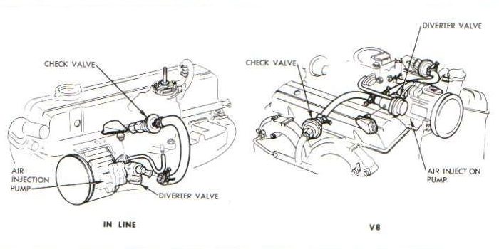
1967 AIR Systems
1967 AIR Systems

In 1968 and 1969, the California and federal emissions requirements were the same and all cars were built to the same 50-state standard. The AIR system was installed on all L6 cars with manual transmissions, all small blocks with manual transmissions, and all Camaros with big blocks. (Chevelles and full-size cars with the 396/325hp engine and TH400 transmission were the only 68-69 Chevrolet big block cars that did not have smog pumps.) Only the automatic L6 and automatic small block Camaros did not have smog pumps, instead they had the simpler Controlled Combustion System. Generally speaking, an automatic car required less aggressive emission control than a manual transmission car because the engine load (and carburetor fuel metering consistency) was more stable and predictable.

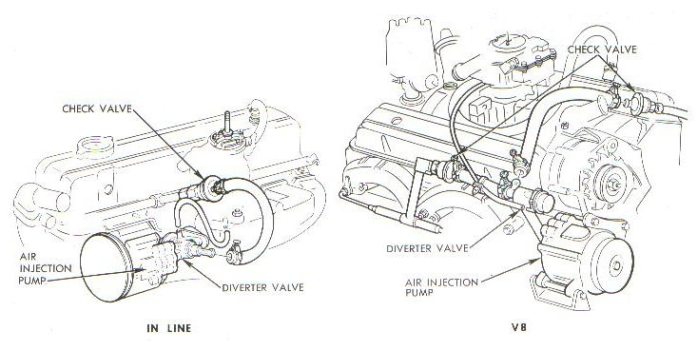
1968 AIR Systems
1968 AIR Systems
1969 AIR Systems
1969 AIR Systems

In 1968, vehicles exported to Canada and other countries did not require the AIR system. RPO KD1 was used to delete the system (if it would have been so equipped otherwise) and 1/4"-18 NPSF straight pipe thread plugs were installed in the manifolds. It is unknown if a credit was issued on the Canadian window stickers for this delete. The Controlled Combustion System was still installed on the exported L6 automatic and small block automatic cars.

In 1969, Canadian cars used the same emission controls as U.S. cars.

PCV became standard on all Chevrolets in 1968 and is still used today on all cars.
 

System Design Changes

To prevent backfiring when there was a rapid increase in manifold vacuum (for instance under a decel condition), the 1966-67 AIR system fuel mixture control valve supplied the intake with extra air to lean out the air-fuel mixture. The approach was not very successful - it resulted in excessive popping noise through the muffler.

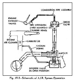
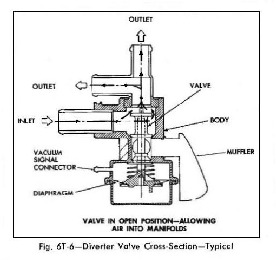
In 1968, the system was redesigned to reduce backfiring (technically called after-firing because it was in the exhaust system) and to make it less complex. When there was a rapid increase in manifold vacuum, the diverter valve, used on 1968 and later systems, momentarily stopped air from being injected into the exhaust ports, thus preventing ignition of the richer exhaust gases.

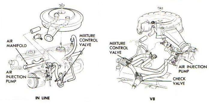
68-69 AIR Diagrams
(Click on either photo to expand it.)
68-69 AIR System Diagram Diverter Valve Diagram
AIR system diagram Diverter valve diagram

The 1966-67 AIR pump used filtered air from the air cleaner. The 1966-67 AIR equipped cars had unique air cleaners to provide this filtered air. The 1968-and-later air pump had an integral filter via the centrifugal smog pump fan. The air cleaners for 68-69 AIR equipped cars were different from the Controlled Combustion System air cleaners due to the ThermAC system on the CSS air cleaners.
 

Smog Pumps

The 67 smog pumps were a serviceable 3-vane design and the pulley attached with 4 bolts. The redesigned 68 AIR system used a non-serviceable 2-vane design with 3 bolts attaching the pulley to the pump. The 68 and 69 smog pump design was used through the mid-70's. The pump housing was die-cast aluminum. The end section, casting # 7801149, is cast iron that was painted semi-gloss black. This casting was widely used, not only on Chevrolet vehicles, but other GM cars too. The machining was different for the other GM makes and will not fit Chevrolet applications.

The 68 pumps used on Z28's and big blocks had a pressure relief valve installed on the side of the pump. The Z28 relief valve has a green plastic plug and the 396 relief valve has a black plastic plug The 68 pumps for L6, 327, and 350 engines and all 69-and-later pumps did not have the pressure relief valve on the pump; it was incorporated into the diverter valve.

67 and 68 V8 pumps were either mounted high on the engine, in front of the intake manifold / carburetor (see 68 diagram), or mounted on the passenger side of the engine. In 1969, as part of the V8 engine layout standardization, the pump was moved to the passenger side, below the alternator.

1967 Smog Pump 1968-69 Smog Pump
1967 Smog pump 1968 Smog Pump

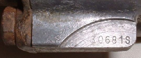
The date code is stamped on a pad on the side of the pump. The date code format is DDDY#P, where DDD = the Julian day, Y = the calendar year, # = 1 or 2, and P = is the configuration code of the pump.

The meaning of # code is thought to be a shift code. 67 pumps were coded 1 or 2 and all 68 and later pumps were coded 1.

The last digit is the configuration code of the pump. The 67 pumps are coded A and C. (67 Corvette pumps are coded P and are unique to that application.) The 68 pumps with a pressure relief valve installed in the pump were coded Y. Non-pressure relief valve 68 pumps were coded Z. 69 and later pumps (without a pressure relief valve) were coded S.

Smog pump date code
30681S = 306th day of (6)8, built without a pressure relief valve.
Smog pump date code

A white smog pump fan was used on smog pumps from 68 to mid-72. Later pumps and service parts used a black fan (though the 68 and 69 service manuals show a black fan!). The pulleys used on the pumps are listed at CRG Pulley Usage.

White Smog Pump Fan
Front and Side View Fan Installed
White Smog Pump Fan White Smog Pump Fan installed


Fuel mixture control valve / Diverter valve

The fuel mixture control valve on 1967 small block engines was located between the distributor and the valve cover. It was mounted on a bracket which in turn was welded to the crankcase vent tube coming out of the lifter valley area at the rear of the block. The mixture valve on big block engines were mounted to a bracket on the RH valve cover.

1967 Fuel Mixture Control Valve 1967 Fuel Mixture Control Valve
Installed on a small block
1967 Fuel Mixture Control Valve 1967 Fuel Mixture Control Valve (and Backfire Valve)

Diverter valves were mounted in multiple ways in 68 (directly to the AIR pump or via an elbow and hose - see the 68 Assembly Instruction Manual (AIM)). The various 69 Camaro V8 diverter valves were externally the same, but had internal calibration differences and hence different part numbers. (Note: Other diverter valves (e.g., 69 truck) may look very similar to 69 Camaro V8 valves, but may have a different output housing or output housing orientation.) As part of the engine layout standardization, 69-and-later Chevrolet V8 cars used a 3942533 extension to connect the diverter to the pump.

Most diverter valves in 68 had a detachable muffler (via a removable clip), though a few have been observed with the muffler crimped on. 69-and-later mufflers were crimped on. The mufflers were plated with gray phospate.

69 Diverter Valve and Extension Close-up of part number, 29295
69 Diverter Valve Diverter Valve part number, 29295

The last five digits of the diverter valve part number were stamped on the diverter valve mounting flange (as shown in the picture above). The broadcast code was ink-stamped on the diverter valve; the codes are shown below.
Note that the 67 Assembly Instruction Manual shows the incorrect part # for the 67 Z28 fuel mixture control valve - the correct number is listed below. The 68 AIM also lists different part numbers than other 68 supporting documentation. The 68 AIM part numbers are believed to be correct.

Fuel mixture control valve (67) and
Diverter valve (68-69) Usage Table
1967 1968 1969
Engine Part No. Part No. Broadcast
Code
Part No. Broadcast
Code
L6 7027093 7024766 FB 7029291 GB
LF7 and 307 7033545 7024767 FD 7029293 GD
L30 and 350 7033546 7024768 FG 7029295 GF
Z28 7024765   DH *
396 and 427 7033547 7024764 DG 7029297 GH
* CT on early vehicles      


Check valves / air manifolds

In 67, the smog pump was connected to the backfire check valves. The left check valve is part # 5354987, while the right check valve is a Y shaped valve (part # 5354988) which also was connected to the fuel mixture control valve.

In 68-and-later cars, the output of the smog pump went through the diverter valve first, then to a backfire valve mounted on each air manifold. The 68-and-later backfire check valves are part # 5361992 and are gold cadmium plated.

The air injection tubes were short pipe extensions (2-13/16 inch long) that were installed before the air manifold was installed. The air manifolds have a greenish/blackish coloration. On the L6 engines, the air manifold installed in the L6 head. On the V8 engines, they were installed into the exhaust manifolds. The threads in the exhaust manifolds for the air manifolds were 1/4"-18 NPSF straight pipe thread.


 CRG Home  Previous/Back
CSS Validated XHTML 1.0 Validated!