C R G CRG Reports Exterior Engine 1967 Model ID
Numbers Decode General Info Interior Transmission 1968 Model ID
Drivetrain Decode Options Underhood Chassis 1969 Model ID

CRG Research Report - © 2018-2024, Camaro Research Group

1967-69 Camaro Driveshafts

Primary Authors - and Kurt Sonen
Last Edit: 6-Apr-2024
Previous Edit: 19-Jan-2024
Original Release: 11-Apr-2018
  1. Driveshaft Usage
  2. Driveshaft Stripes
  3. Universal Joints
  4. Acknowledgements
 

Introduction

The driveshafts (propeller shafts) for 67-69 Camaros were generally very similar. The shafts have a diameter of 2.75 inches, a wall thickness of 0.065 inches, and were about 50 inches long. The differences in the driveshafts were: transmission yoke and driveshaft length. There were two different output shaft yokes. Most transmissions (both automatic and manual) used the 27 spline yoke. The Turbo-Hydramatic 400 (TH400) used the larger 32 spline output shaft yoke. Different driveshaft lengths were needed due to big block engine location differences.

Driveshafts were balanced within 3/16 in-oz by welding various sized balancing slugs to the ends of the driveshaft as required (shown in the pictures below). The balance specification stated that testing was to be done at 3500 rpm.

Note: All lengths are measured from centerline to centerline of the universal joints.  

Driveshafts for 1967 and 1968

In 1967 and 1968, Camaros with the 6-cylinder engine or the small block engine used a driveshaft with a length of 49.96" and the smaller 27-spline yoke output shaft with a seal diameter of 1.502 inches. 67-68 Camaros with the 396 engine received different engine mounting brackets. Due to these frame mounts, big block engines are offset approximately 1 inch toward the passenger side of the engine and 0.5 inches forward. Because of this, big block cars with manual transmissions have a driveshaft that is 0.5 inch longer (50.46 inches).

Most transmissions have an overall length of approximately 27.75 inches. (For manual transmissions, this includes 6.375 inches for the bellhousing and 21.25 for the transmission itself.) The TH400 is about 0.5 inch longer, or 28.25 inches. Because of this, the driveshaft length for the big block and TH400 combination is the same length as the L6 and SBC engines. But the TH400 uses a larger 32 spline output shaft and requires the larger yoke with a 1.875 inch outside diameter.

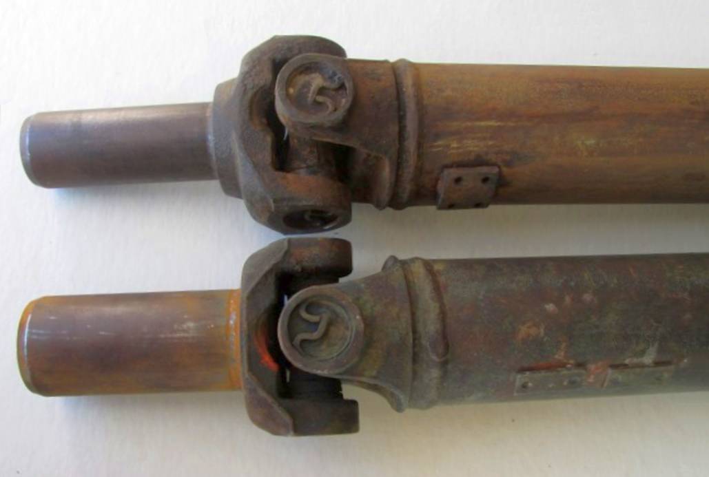
27 Spline (top) and 32 spline / TH400 (bottom) slip yokes.
Note the balancing weights on the tubes.
27 Spline and 32 spline yokes
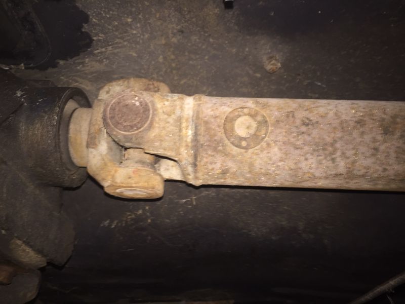
1967 Camaro TH400 driveshaft installed in the car.
Note balancing weight.
1967 TH400 driveshaft


Driveshafts for 1969

All 1969 Camaro driveshafts are 49.56 inches in length. In 1969, big block engines were still offset toward the passenger side, but the "front to back" engine mounting location was now only 1/4 inch forward compared to the the L6 and SBC engines.

The yoke design for all applications was strengthened in 1969 by adding metal to the internally splined neck. The yoke was also lengthened, which allowed it to be used with not only all the L6 and small block applications, but also the big block manual transmission application.

The TH400 yoke design was also strengthened, but it still had the larger trunions and u-joints. Hence a unique driveshaft was still required for the TH400 applications. The document below indicates that the TH400 yoke was also going to be used on 396 and 427 with manual transmission applications, but this was not implemented until 1970 on the M22 and 1971 on other Muncie models.

There was also a third driveshaft used in 69 for all TH350 applications. The length and the yoke are the same as the 3950194 driveshaft. It is unknown why this driveshaft was required.

Service News - Yoke design change for 1969.
68 and 69 Yoke comparison
Communications Newsletter - Yoke design change for 1969.
68 and 69 Yoke comparison

Camaro Driveshaft Usage
 Year  Engine(s) Transmission AIM
Part number
Service
Part number
Length Yoke diameter Stripes
1967  L6 and SBC  Manual, PG 3899009 3910061 49.96" 1.5" orange/white
1968
1967 BBC Manual n/a 3914190 50.46" 1.5" orange/green/white
1968
1967 BBC TH400 n/a 7801406
3958031
49.96" 1.875" orange/green/pink
1968
1968 SBC TH350* 3945544 3950194 49.56" 1.5"
1969 L6, SBC, 396 Manual, PG 3945540 3950194 49.56" 1.5" orange/white
1969 L6 and SBC TH350 3980952 n/a 49.56" 1.5" orange/blue/pink
1969 BBC TH400 3945543 3950196 49.56" 1.875" orange/green/purple
1969 427 Muncie 49.56" 1.5" orange/brown/purple
* TH350 used late in the 1968 model year on 327/275hp cars as part of an internal GM test fleet.

Note: The AIM (Assembly Instruction Manual) part numbers are for the driveshafts used in production. These were an assembly consisting of the tube, u-joints, and yoke. The service part consisted of only the the tube with the front and rear welded trunnions.  

Driveshaft Stripes

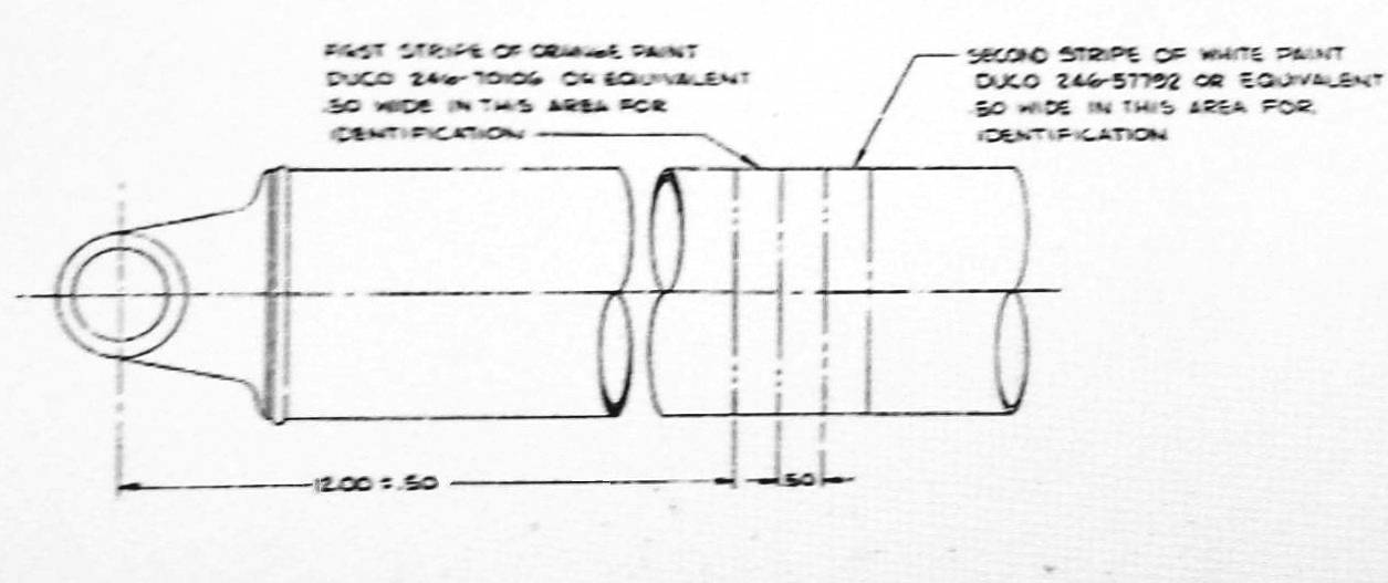
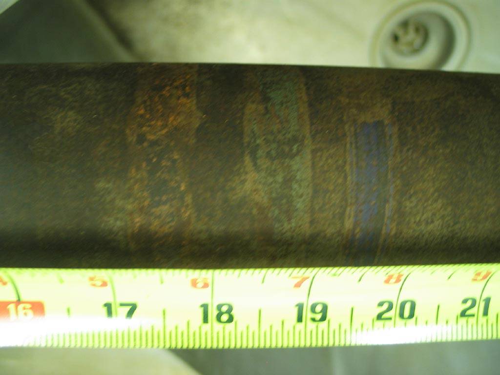
Stripes were added to the driveshaft as identification in the assembly plant. The stripes listed in the table above have been confirmed via the part print. Below are some examples of the stripes found on first generation Camaro driveshafts. The stripes were added during the driveshaft balancing process with a brush while the shaft was spinning. Since these were done by hand, there are variations in location on the shaft, stripe width, and stripe spacing.
Stripe diagram for 3945540 driveshaft
Stripe diagram

1967 Camaro, small block with Powerglide
1967 L48 with PG
1968 Camaro, small block with Muncie
1968 Z28 with Muncie


1968 Camaro, 396 with TH400
1968 L35 with TH400
1968 Camaro, 396 with Muncie
1968 L78 with Muncie


1969 Camaro, 396 with TH400
1969 L35 with TH400


Universal Joint Type

Most Camaro driveshafts used the Dana design universal joints (u-joints) with the typical external retaining ring design. The only exception is that 1967 TH400 and most 1968 TH400 driveshafts received heavy-duty Saginaw design u-joints. This u-joint has a bearing assembly that is retained by nylon injected into the yokes and trunnions, instead of the snap ring design. Both u-joint styles used the sealed "extended-life design", i.e. they did not have any grease fittings.

In 1969, the pinion flange on the axle switched from u-bolts/nuts to straps and capscrews to retain the u-joint.

Standard Universal Joint with Snap Rings
Standard U Joint
Heavy Duty Universal Joint with Nylon Injected
Heavy Duty U Joint


Yoke offset

The 67-69 in-line six cylinder (L6) and small-block driveshafts had the yokes offset (or "clocked") by 32 degrees. The 67-68 big-block driveshafts had the yokes in-line, with no offset. This may be to help limit vibration, since the engine and transmission are not in direct line with the rear axle (due to the engine and transmission being offset toward the passenger side). Data for 69 big-block driveshafts is not completely clear. Research continues, but it appears that at least the TH400 cars and L72 manual transmission cars had yokes in line.

Offset Yokes
Offset Yokes
In-Line Yokes
In-Line Yokes


Acknowledgements

The authors would like to sincerely thank the other members of CRG for their assistance with this report and also those who gave permission for use of their photos.

You can help improve future revisions of this report. We would appreciate notes of verified differences or other things that you feel are pertinent on this subject. Digital photos of driveshaft stripes from original low mileage cars would be helpful as well. In January 2022 we were able to determine with a fair amount of certainty that cars with the L72 engine and a Muncie transmission had a driveshaft with a different stripe combination. Research continues on the topic.


 CRG Home  Previous/Back
CSS Validated XHTML 1.0 Validated!