CRG Research Report - © 2020, Camaro Research Group
1967-69 Camaro Differential Carriers and Associated Parts
Author -
Reviewed by the CRG
Last Edit: 30-Dec-2025
Previous Edits: 26-Jul-2024
Original Release: 11-Mar-2020
|
-
Introduction
-
Carrier Differences
-
COPO Carriers
-
Carrier Groups
-
Ring and Pinion
-
Internal Carrier Parts
-
Other Parts
-
Part Failures / Racing Use
Introduction
The rear axle differential allows the outer drive wheel to rotate faster than the inner drive wheel
during a turn via a planetary gear train. The differential carrier case (often commonly referred to as the
carrier) in this gear train is located inside the center section of the axle housing (differential carrier and
axle tube assembly). It transfers motion from the driveshaft to the axle shafts using a ring gear and pinion
shaft. The carrier is held in the housing with 2 caps that have 2 bolts each. The axle shafts insert into
the carrier, and the axle shafts are held in with c-clips. There are two main types of stock carriers, open
and limited slip. Limited slip carriers have a set of clutches that effectively connect the two axles together
so both wheels will spin at the same rate. The clutches still allow for different axle speeds while going
around corners. Here is an excellent video
that explains the operation of the limited slip differential. GM started offering limited slip differentials
as early as 1957. These were sold under several names. Chevrolet used the trade name Positraction, which
is often shortened to posi. Standard axles typically had an open (non-posi) carrier.
Positraction was available at an additional cost (option G80), and was mandatory on the 4.10, 4.56 and 4.88
ratios. Positraction was optional for Z28's with 3.73. In 1969, positraction was also a requirement on all
non-Z28 cars with the 3.73 ratio. (In 67-68, it appears that positraction was not a requirement with the
3.73 ratio for non-Z28 cars.)
If an axle has an open carrier, then it can be converted to a posi by installing a posi carrier of
the same series. The pinion does not have to be removed, but the ring gear does have to be
swapped over from the open carrier to the posi carrier. The backlash and side shims will need
to be checked and may need adjustment. Open carriers can be converted to posi by installing aftermarket
parts. These would include a spool or a mini-spool or kits such the POWERTRAX Lock Right Locker.
However, these are generally not as street friendly as an original posi.
Camaro rear axle cross section diagram.

|
|
Exploded view of positraction carriers.

|
|
The left diagram above is a rear axle cross section from a 1968 GM parts manual. This shows some of the
parts that will be discussed in this report. The image on the right is an exploded view of the
positraction components from a 1968 GM parts manual. The Eaton type posi was used in all 1967
to 1969 Camaros, and is shown in the lower part of the image on the right. The upper part of
the image is for a Dana posi. Click on each image to enlarge.
Carrier Differences
First let's examine the visual differences in the carriers. Posi carriers have 4 springs and 2 plates
inside the carrier that preload the set of clutches. Open carriers do not have these springs, plates
and clutches.
Posi Carrier showing the preload pack - springs and plates between the axle gears.

|
|
Open carriers did not have springs inside the case.

|
|
The differences on the non-ring gear side or passenger side (as installed in the housing) of the
carriers are shown below. The posi carrier requires extra space for the clutches.
There is a casting date in Julian format on this end of the case. In the
example below, the casting date of 44 = February 13. There is no year indicated in the casting date.
The alternate location for the assembly date
of the posi unit is sometimes located on the balancing boss on this end of the case.
Non-ring gear side of an open carrier (with bearing installed).

|
|
Non-ring gear side of a posi carrier (with bearing installed).

|
|
Casting date and balancing boss locations.

|
|
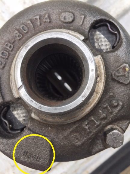
The external castings of posi carriers are different. The ring gear side of posi carriers are
shown below. The amount of webbing increases as you go from a 2-series carrier to a 4-series carrier. This
helps make the 4-series carrier the strongest and the best for high torque use. A coded assembly date
is usually stamped on the outside edge of the ring gear flange of the case. The format is month, day, and
calendar year using a letter, number, letter format. The one shown below is D 11 J, which corresponds to
April 11, 1969. The author is fairly certain that J was used for the year 1969. More research is in progress
to verify the letter codes for other years, but it appears that G was used for 1966, H for 1967 and I for 1968.
Again, these are calendar year.
Ring gear side of a 2-series posi.

|
|
Ring gear side of a 4-series posi.

|
|
Posi assembly date.

|
|
COPO carriers and internal parts
The 1969 COPO 427 cars were equipped with a special axle. The 4-series carrier (GM part number
3916234) used in these axles had the same casting number as the regular 4-series carrier, but the
internals were not the same. The COPO carrier was machined differently, so it could handle larger
internal gears. The axle side gears used in COPO units have 16 teeth. Standard axle gears have 18
teeth. The pinion gears used in COPO units are noticeably larger than those used in standard posis,
but both have 10 teeth. The pinion gears used in COPO carriers are actually the same as those used in
standard open carriers. The clutch plates are the same for the COPO and regular 4-series posi units,
with 18 plates (9 per side). There are some other parts that are specific to the COPO carriers. These
include different springs (natural steel color - rated at 75 pounds each) and different spring plates.
COPO spring plates have a round hole, while standard posi spring plates are oblong. Most COPO carriers
have a "small window" on the side of the case opposite to the large opening where the clutch pack is
inserted into the case. See reference pics below for examples of the internal parts.
Small window on case.

|
|
COPO carrier internal parts.

|
|
Large window on case.

|
|
Carrier Groups
There are two carrier groups for 10-bolts and three carrier groups for 12-bolts. Those
are outlined below according ratio. 2-series and 3-series carriers were available in either open
or posi. There were no original 4-series 10-bolt open or posi carriers, and there were no 4-series
12-bolt open carriers.
Chevy 10-bolt car (8.2"): 2-series is 2.56 and 2.73. 3-series is 3.08, 3.36 and 3.55 (other ratios
available in aftermarket).
Chevy 12-bolt car (8.875"): 2-series is 2.56 and 2.73. 3-series is 3.07, 3.31, 3.55 and 3.73 (3.42
and 3.90 in aftermarket). 4-series is 4.10, 4.56 and 4.88 (5.13 GM over the counter and others in
aftermarket).
| 2-series 12-bolt posi |
3-series 12-bolt posi |
4-series 12-bolt posi |

|

|

|
Axle Carrier Casting Numbers
| Type |
2-series |
3-series |
4-series |
| open 10-bolt |
3910821 |
3878439 |
n/a |
| posi 10-bolt |
ED32118 |
EDB30116 |
n/a |
| open 12-bolt |
3869789 |
3852989 |
n/a |
| posi 12-bolt |
ED32088 |
30140PM1 |
EDB30174 |
All 12-bolt carriers with a GM part number were produced by Eaton.
Carriers have different offsets for the ring gear location in the housing. The 4-series carrier
has the ring gear closest to the center of the housing, and thus the size of the gear end of the
pinion is smaller. 2-series carriers have the ring gear offset farthest toward the drivers side,
and the gear end of the pinion is the largest (compared to 3- and 4-series gear sets). See the pinion
pics farther down in this report.
The left photo below shows the two sizes of the window on the backside of the case
(the side opposite of where the preload pack is installed). There is a large window version
and a small window version. The small window cases are associated with most 4-series carriers and some
3-series carriers. The large window makes it easier to install the internal gears.
Carrier ring gear offset comparison. From left to right, 2-series, 3-series, 4-series.

|
|
2.2" offset of 4-series (left) and 1.8" offset of 3-series (right).

|
|
Ring and Pinion
The number of teeth on the ring and pinion determine the ratio. Below is a chart with the individual
part numbers. If new gears were needed, these were sold as a set with a different part number.
Stock 10-bolt axle ratios included 2.56, 2.73, 3.08, 3.36 and 3.55.
Stock 12-bolt axle ratios included 2.56, 2.73, 3.07, 3.31, 3.55, 3.73, 4.10, 4.56 and 4.88.
The part numbers associated with each gear set are in the table below.
10-bolt Ring and Pinion Part Numbers
(tooth count in parantheses)
| 10-bolt Ratio |
Ring Gear |
Pinion |
Set |
| 2.56 |
3917185 (41) |
3917184 (16) |
3961426 |
| 2.73 |
3910823 (41) |
3910818 (15) |
3961425 |
| 3.08 |
3790629 (37) |
3880042 (12) |
3961413 |
| 3.36 |
3790628 (37) |
3880044 (11) |
3961412 |
| 3.55 |
3790627 (39) |
3880046 (11) |
3961411 |
|
|
12-bolt Ring and Pinion Part Numbers
(tooth count in parantheses)
| 12-bolt Ratio |
Ring Gear |
Pinion |
Set |
| 2.56 |
3871038 (41) |
3871041 (16) |
3961434 |
| 2.73 |
3910818 (41) |
3910823 (15) |
3961425 |
| 3.07 |
3863691 (43) |
3853003 (14) |
3961407 |
| 3.31 |
3862689 (43) |
3862693 (13) |
3961405 |
| 3.55 |
3853010 (39) |
3853008 (11) |
3961406 |
| 3.73 |
3862525 (41) |
3862513 (11) |
3961408 |
| 4.10 |
3862526 (41) |
3862514 (10) |
3961409 |
| 4.56 |
3862527 (41) |
3862515 (9) |
3961410 |
| 4.88 |
3862528 (39) |
3862516 (8) |
3961404 |
|
Not all axle ratio combinations were used in production. Specifially, in 1967, the 2.73 posi axle was
of such low volume that all 2.73 axle ratio with positraction were 12-bolt axles. This was independent
of other options on the car. Even some 6 cylinder cars have been observed with 12-bolt 2.73 posi axles.
The 4.56 and 4.88 ratios were available as standard options in 1967 and 1968, but not in 1969.
Everyone thinks of the 427 with 4.10 axle when COPO is mentioned, but in 1969 the 4.56 and 4.88 ratios were only
available with COPO 9511. One car in 1968 has been found with COPO 9511 with 4.88 gears. All of the COPO ring and pinion sets received a special heat treatment and different
part numbers than the standard gears.
COPO Ring and Pinion Part Numbers
| Ratio |
Ring Gear |
Pinion |
Set |
| 4.10 |
3916226 |
3916228 |
3917971 |
| 4.56 |
3916230 |
3916231 |
3917973 |
| 4.88 |
3916232 |
3916233 |
3917972 |
As noted earlier, the size of the pinion gear varied based on the gear ratio. In general, the pinion
gear size gets smaller as the gear ratio increases numerically (2.73 to 4.88). See pic below.
Comparison of pinion gear size. From left to right - 2.73, 3.07, 4.10, 4.88.

|
|
The information stamped on the edge of the ring gear is typically in the form of part number, pinion
tooth count, ring gear count, one or two digit month and two digit year of manufacture. The same
information is stamped on the large end of the pinion shaft, but the order may not be exactly the same.
4.10 GM gears dated November 1967.

|
|
4.88 GM gears dated December 1967.

|
|
Internal Carrier Parts
There were different versions of some of the internal parts. Several different clutch spring rates
were available. Stock springs were natural steel color and rated at 50 pounds each.
Replacement springs had green paint and had GM part number 3890899 - Eaton ED 7976.
Replacement springs with yellow paint were rated at 75 pounds each with part number 3890860 -
Eaton ED 72043. Higher rate springs were available, including some thicker springs with
yellow paint rated at 100 pounds each.
The springs in aftermarket Moroso Brute Strength posi units are noticeably thicker with fewer
coils, rated at 200 pounds each. The Brute Strength spring plates are also thicker. See picture below for
comparison, but note that the green GM spring is not compressed. The standard spring plates were
part number 3869230.
Regular posi spring plates and springs. Note hint of yellow paint on springs.

|
|
Preload pack, springs and plates.

|
|
Comparison of Brute Strength spring to original GM spring.

|
|
The clutch pack plates and discs are located between the differential side gears and the carrier housing.
The clutch packs create friction between the side gears and the carrier housing and limit the speed
differential between the side gears and the ring gear.
These are stacked by alternating the two types (5 eared plates and 4 splined discs per side).
The splined discs have teeth on the inner edge that lock onto the axle gear. The other plates
have 2 ears that lock into the carrier with power lock disc guides (also called case bushings).
The plates all have a "waffled" type surface.
Reference the diagram of a positraction carrier image earlier in this report.
Clutch pack rebuild kits are available. These were originally part number 9781862, replaced by 483722
in December 1971. The kit had 4 case bushings (power lock disc guides) and the plate/disc pack.
However, the replacement clutch discs had slots in them, unlike the original factory parts - the original clutch pack
discs were solid.
Carbon fiber rebuild kits are also available. These carbon fiber kits have 6 carbon fiber discs and 8
metal plates. The carbon fiber discs are similar in size and shape to the originals. It
appears that there were 2 different clutch packs for the 8.2 ten bolt posi units. The part number used
for 1965 to 1968 units was 3888070. Further research is needed on the 10-bolt clutch packs.
NOS 12-bolt GM differential clutch pack

|
|
GM clutch plates. From left to right - 12-bolt replacement,
12-bolt original, 10-bolt 8.5 plate.

|
|
Carbon fiber clutch pack.

|
|
Other Parts
As mentioned earlier, inside each carrier housing there are pinion gears and axle gears. The axle gears
have splines inside and the axles fit into these splines. Twelve bolt side gears (and axles) have 30
splines, while 8.2 ten bolt carrier side gears and axles have 28 splines. C-clips hold the axles into
the side gears and carrier.
A=pinion gear thrust washers, B=pinion gears, C=axle gears.

|
|
28 spline axle for 8.2 carrier.

|
|
Axle C-Clip which holds the axle into the carrier.

|
|
There is a bolt on the non ring gear end of the carrier. This bolt holds the cross shaft (differential
side pinion shaft) inside the carrier. The technical name for the bolt is diffential pinion shaft lock
screw. In order to remove the cross shaft or pinion gears, this bolt must be taken out first.
The length of the bolt for posi carriers is about 2 5/8 inches long, not including the head of the bolt.
The bolt for open carriers is shorter, about 2 inches in length.
Pinion shaft lock screws. From top to bottom - original non-posi, original
posi, aftermarket posi.

|
|
Location of pinion lock shaft screw.

|
|
Pinion shaft and lock screw.

|
|
The pinion yoke is located at the most forward part of the axle housing and connects to the
driveshaft. The yoke slides onto the splined end of the pinion shaft and is attached to the pinion
with a washer and nut. The size of the u-joint used with the pinion yoke
depended on the application. For 1967 and 1968, all 12-bolt axles, except those with the TH400
transmission, used a 1310 u-joint with a pinion yoke that had part number 3878972 (number on the yoke
is 974). Camaros with the TH400 transmission had 12-bolts with a yoke that used a 1330 u-joint,
part number 3879208 (number on the part is 9210). In 1967 and 1968, the 1310 u-joints were attached to
the yoke with u-bolts, washers and nuts while the 1330 u-joints were attached with straps and bolts.
In 1969, a 1310 u-joint was used for all applications, and it was attached with straps and bolts.
This pinion yoke - also used in 1970 - was part number 3954393 (number on the part is 4394). All
12-bolt pinion yokes have 30 splines, while 10-bolt pinion yokes have 25 splines. The part number for
the 10-bolt yoke, for all three years, was 3878968.
The 9210 pinion yokes used with the 1330 u-joint are visibly wider than the 974 and 4394 yokes.
The 4394 yoke used in 1969-70 is similar to the 974 pinion yoke in size, but it uses bolts and straps
for driveshaft attachment. Yokes had a natural steel finish (they were masked off when the axle was
painted). Hardware was normally natural steel or phosphate coated.
974 (L) and 9210 (R) pinion yokes with u-bolts and straps underneath

|
|
4394 pinion yoke used in 1969 and 1970.

|
|
Original unrestored August 1969 4394 pinion yoke.

|
|
A fill plug is located on the passenger side of the center section of the axle housing.
12-bolt rear ends typically use about 2 to 2.5 quarts of gear lubricant and one bottle of
limited slip axle lubricant additive (if it has a posi unit installed). Fill until fluid reaches the
bottom of the hole with the car sitting level.
In 1967, the fill plug was about 1 inch in diameter (3/4"-14 NPT). In 1968 and 1969 the fill plug decreased
in size to about 3/4 inch in diameter (1/2"-14 NPT). The exact date that the plug size changed is not known,
but seems to be in the late summer of 1967. Posi plugs for both the 12-bolt and 10-bolt had a lip
on the plug to retain the red plastic tag. Non-posi plugs do not have a lip. Plug part numbers for 1967 were
3866433 (posi with tag) and 3779764 (non posi). Plug part numbers for 1968 and 1969 were 3931171 (posi with
tag) and 3923429 (non posi).
All axles with positraction received a red plastic tag on the fill plug. The tag used for 1967 to 1969
Camaros has the following wording "USE POSITRACTION DIFF. LUBRICANT ONLY". The hole in the tag is slightly
larger in 1967 compared to 1968 and 1969, because the 1967 plug is larger.
Rear axle plugs. From left to right - 68 and 69 posi plug, 67 posi plug,
67 open plug, Lisle aftermarket #3 magnetic plug for 67 and box.

|
|
Red posi tag installed.

|
|
Side view. From left to right - 68 and 69 posi plug, 67 posi plug, 67 open plug,
Lisle aftermarket #3 magnetic plug for 67.

|
Part Failures / Racing Use
The original differential parts held up well to normal street abuse. Failures were more common at
the track with high RPM launches and sticky tires. There were incidents of axles or c-clips breaking while
drag racing, including on ZL1 car #1 and at least one 69 Yenko Camaro. Case failures happened, but were
not common. Some people think the small window cases were stronger, due to having a larger amount of
metal in the case. Others believe the small window cases were weaker, because the hole was rough cast
and could be an area where stress fractures could occur.
There is a common misconception that COPO rear ends used larger diameter axle bearings. All first generation
Camaro assembly plant installed axles used the same size axle bearings. Larger diameter axle bearings (and
larger diameter axle shafts at the wheel end of the shaft) were found in 12-bolt axles used in trucks, full
size cars (such as Impalas) and in over the counter HD Service Package rear ends. The larger diameter axle shafts
and bearings significantly improved durability.
Jerry MacNeish, who has 50 years experience drag racing and working on rear ends, says that service
parts did not seem to hold up as well as original components and had higher failure rates. Problems
were noted with axle shafts, pinion gear shafts, internal carrier pinion gears, and the "slotted" type
service clutch packs. Because of this, Jerry turned to the November 1970 Super Sport Equipment parts
book and learned of parts like the COPO-only 3916234 carrier and the 3955877 carrier (previous part number was
3915477 until May 1972). The GM 234 carrier tended to be favored by drag racers. Original over the counter
HD Service Package rear ends used the 477 carrier (877 after May 1972). The GM 477 and 877 carriers had 11 clutches
per side (22 total) and smaller heat treated internal gears. It tended to be used mostly by Trans Am road racers and
was also sold by Moroso as their "Brute Strength" carrier. Special heat treated R-50 High Impact ring and pinion
sets were available in the 4.88 and 5.13 gear ratios (GM part numbers 3961192 and 3961195).
Acknowledgements
Thanks to many of the CRG members for their assistance, review and support with this report. Special
thanks to Freddie, aka "big gear head" and Jim Mitschke - JDRace - for permission to use of some of
their photos and their review of some of the technical information.
If you have information that differs from what was in this report, I would like to hear from you. This
report was done with the best information available, but, as always, there is room for improvement.
