


| C R G | CRG Reports | Exterior | Engine | 1967 Model ID |
| Numbers Decode | General Info | Interior | Transmission | 1968 Model ID |
| Drivetrain Decode | Options | Underhood | Chassis | 1969 Model ID |
©1998-2026, Camaro Research Group
Edited by
and
Version: Monday, 02-Mar-2026 01:51:07 EST
Engine options introduced mid-year 67 are shown in the late 67 column. Engine options in 69 that were available all year are centered. Engines available until 1/1/69 are shown under the early column and their replacements are shown under the late column. See the COPO article for information about the 1969 L78 and L72 production totals.
     ENGINE PRODUCTION VOLUMES
                                     1967           1968           1969
                                         late                 early    late
Base L6
  L26     230ci/140HP  L6 1BC      20,643          22,322         17,588
Optional L6
  L22     250ci/155HP  L6 1BC      38,165          28,647         18,660
Base non-SS V8
  LF7     327ci/210HP  V8 2BC     102,409         124,870      44,746
  L14     307ci/200HP  V8 2BC                                        68,487
Optional higher hp non-SS V8
  L30     327ci/275HP  V8 4BC      25,287          21,686
  LM1     350ci/255HP  V8 4BC                                  10,406
  L65     350ci/250HP  V8 2BC                                        26,898
SS models
  L48     350ci/295HP* V8 4BC      29,270          12,496         22,339
  L35     396ci/325HP  V8 4BC          4,003       10,773          6,752
  L34     396ci/350HP  V8 4BC                       2,579          2,018
  L78     396ci/375HP  V8 4BC          1,138        4,575          3,823 ^
  L78/L89 396ci/375HP  V8 4BC **                      272            311
Z28
  Z28     302ci/290HP  V8 4BC            602        7,199         20,302
COPO models
  L72     427ci/425HP  V8 4BC #                                      997 ^
  ZL1     427ci/430HP  V8 4BC ##                                      69
---------------------------------

 * rated 300HP in 1969
 ** Al head option
 # COPO 9561, cast-iron
 ## COPO 9560, Al block/heads
 ^ L78 total adjusted for COPO production. See COPO article for more info.
|
| 67 Engine Usage | 68 Engine Usage | 69 Engine Usage |
|
|
|
|
In order to gain engine compartment clearance, big block (BB) engines were offset 1/2 inch to the right (towards the passenger side) by means of asymmetric brackets. 1967-68 BB frame mount brackets are 2-1/2 inches wide (but not the same as SB) and use the same engine mounts as 67-68 302ci and 350ci. For 69, BB frame mount brackets were redesigned to use the new thicker, narrower, engine mount also used by 302ci and 350ci. BBC bracket pairs are easily spotted because the left bracket is noticeably taller than the right in order to achieve the engine offset.
Note that the frame mount brackets and the engine mounts below are grouped together by functionality. The OEM engine mounts may have had different part numbers in the different applications and different years, but are functionally the same within a grouping. The original frame mount part numbers are listed.
   Frame Mount Brackets      Part No. (L, R)
 ------------------------   -----------------
 L6
     67-69                  3892731, 3892732

 V8
   1) 67-68 302, 327, 350   3892733, 3892734
      and 69 327/307        3955183, 3955184
   2) 67-68 396             3912597, 3912598
   3) 69 302 and 350        3945507, 3945508
   4) 69 396                3950113, 3950114
|
|
    Engine Mounts               Part No.
 --------------------         ------------
 L6   a) 67-early 68            3866247
      b) late 68-69             3932799

 V8   a) 67-68 327 non-PS
         67-68 327 PS right
            69 327/307
      b) 67-68 327 PS left
      c) 67-68 302, 350, 396
      d) 69 302, 350, 396
Quoting from the Chevrolet Dealer Service Information Bulletin, 69-I-1, dated 19 Sept, 1968:
|
Most service parts were produced specifically for service. Production engines and transmissions were generally not used as service parts.
| 1967 BB with smog RH Valve Cover w/ bracket |
Stant Oil Cap | |

|

|
The Camaro big block valve covers used on the 396 and 427 engines were basically the same for 1967 through 1969. They had the same shape and all had oil drippers spot-welded on the inside of the cover which created the "dimples" on the outside of the cover. But the brackets attached to the valve covers changed every year.
Righthand - The righthand side valve covers were similar all three years.
The oil cap was located on the righthand valve cover and was a twist-on style
(later valve covers used a push-in rubber plug). The 1967 396 with smog had
a one-year-only unique cover which had a bracket on the valve cover
for the fuel mixture control valve.
Both 67 396 (with and without smog) RH valve covers have the spark plug wire stand
welded in the center of the valve cover. Whereas the 68 and 69 RH valve covers have
the spark plug wire stand located rearward, almost directly under the crankcase
vent tube hole.
Lefthand - The lefthand side big block valve covers had three features in common all three years - a slanted end for wiper motor clearance when removing the cover, a dimple for rocker arm clearance and for the oil dripper inside the valve cover, and the rear spark plug wire stand located forward of the rear bolt hole, also to clear the wiper motor. Both Camaros and Nova had the spark plug wire stand in this location. Chevelles and full-size Chevrolets had the stand rearward of the rear bolt hole.
| Close-up of slanted end of the LH cover |
Close-up of LH dimple and oil dripper |
LH cover for 68-69 Chevelles and full-size Chevrolets |

|

|

|
The changes in the LH valve cover are all related to the temperature sender wiring. In 1967, the sender was mounted in the front of the intake and there were two temperature sender wire clip tabs along the intake side of the valve cover for routing the wiring. In 1968, there are no clips on the valve cover because the temperature sender was in the head and the wiring was part of the alternator harness. In 1969, the alternator moved to the other side of the engine and the temperature sender wire came out at the firewall and down the exhaust manifold side to the temperature sender in the head. The 69 BB valve cover had one wire tab (which was dip-coated with plastic) on the exhaust manifold side of the valve cover for this wiring.
| Close-up of 67 wiring clip | 1968 Camaro BB Valve Covers | Close-up of 69 wiring clip |
")
|

|

|
These download files are the copyright property of the Camaro Research Group, and are subject to the same restrictions as any other data on our web site. Do not download any of these files unless you can comply with these restrictions.
Click (or Shift-Click) to download the listings in PDF format.First-generation Camaro distributors used an aluminum distributor housing with single point ignition. The one exception to this is the ZL1 427 engine which used a cast iron housing distributor with magnetic pulse ignition. The aluminum housings were stamped with the part number and the production date. The date code was in a YMDD format, e.g. 7H17 (1967 Aug 17). A color stripe was applied to the distributor to help the engine assembly workers identify the distributor without looking at the part number. The cast iron housings were not stamped, they had an aluminum band stamped with the identification number and date. The distributors varied in the configuration of the distributor weights, distributor cam, and vacuum advance units. The distributor cams are listed in the table below.

|
|
|
Notes:
* - one GM source shows the 1968 manual trans applications used the auto trans part in
early 68 production and some may have used the 69 part in late production - neither case has
been observed in a vehicle.
# - some GM sources show the 1969 L34 auto uses a 1111497, others show 1111499. Limited
vehicle data supports the 497 usage, which also follows the same usage pattern as 1968.
|
|
|
|||||||||||||||||||||||||||||||||||||||||||||||||||||||||||||||||||||||||||||||||||||||||||||||||||||||||||||||||||||||||||||||||||||||
From the AIMs and broadcast sheets and car data (note that only the last three digits were embossed on the coil):

|

|
67-69 L6: 1115208
67 V8:
1115267 - used on many applications including LF7(base 327), L35, and L78.
1115270 and another coil (possibly 290) - used on L30 and SS350 cars. It apppears that the
ignition resistance wire changed from 1.8 ohm to 1.3 ohm in production and so the coil may be an
early vs late usage.
68 V8:
1115293 - all engines except Z28
1115202 - early Z28
1115298 - late Z28 (changeover was about Jan 68)
69 V8:
1115293 - used on all engines except below
1115298 - Z28
1115270 - small block (Z28 and SS350) with cowl hood
1115210 - ZL1 TI units
|
|
Chevrolet had two basic starter designs that were used from 1963 to 1985. The size of the
ring gear on the flexplate or flywheel determined which starter design was used.
- The smaller 153-tooth ring gear was 12.75 inches in diameter. This design used a starter
with the straight-line mounting bolt housing made of aluminum, with 2 different length bolts.
Manual transmission cars used the 403 bellhousing.
- The larger 168-tooth ring gear was 14 inches in diameter. It used a starter with a
staggered mounting bolt housing made of cast-iron, with equal length bolts. Manual
transmission cars used the 621 bellhousing.
The listings for starters in GM documentation vary significantly and part numbers were consolidated for service to reduce the number of service parts; we are not addressing either service part use or physically interchangeable parts. The difference between starters, that were otherwise the same external form and fit, is the torque output due to different internal component parts.
The starter usages below have all been confirmed via original cars or production
documentation (e.g. the AIM and chassis broadcast sheets).
Here are a few notations about the applications.
MT = manual transmission, AT = automatic transmission.
* The starter for a 1967 L6 with an automatic transmission has not been confirmed.
The starter used on the 1967 327's changed mid-way through the year. There is not
enough data yet to pin down the changeover date beyond that it happened in the spring of 67.
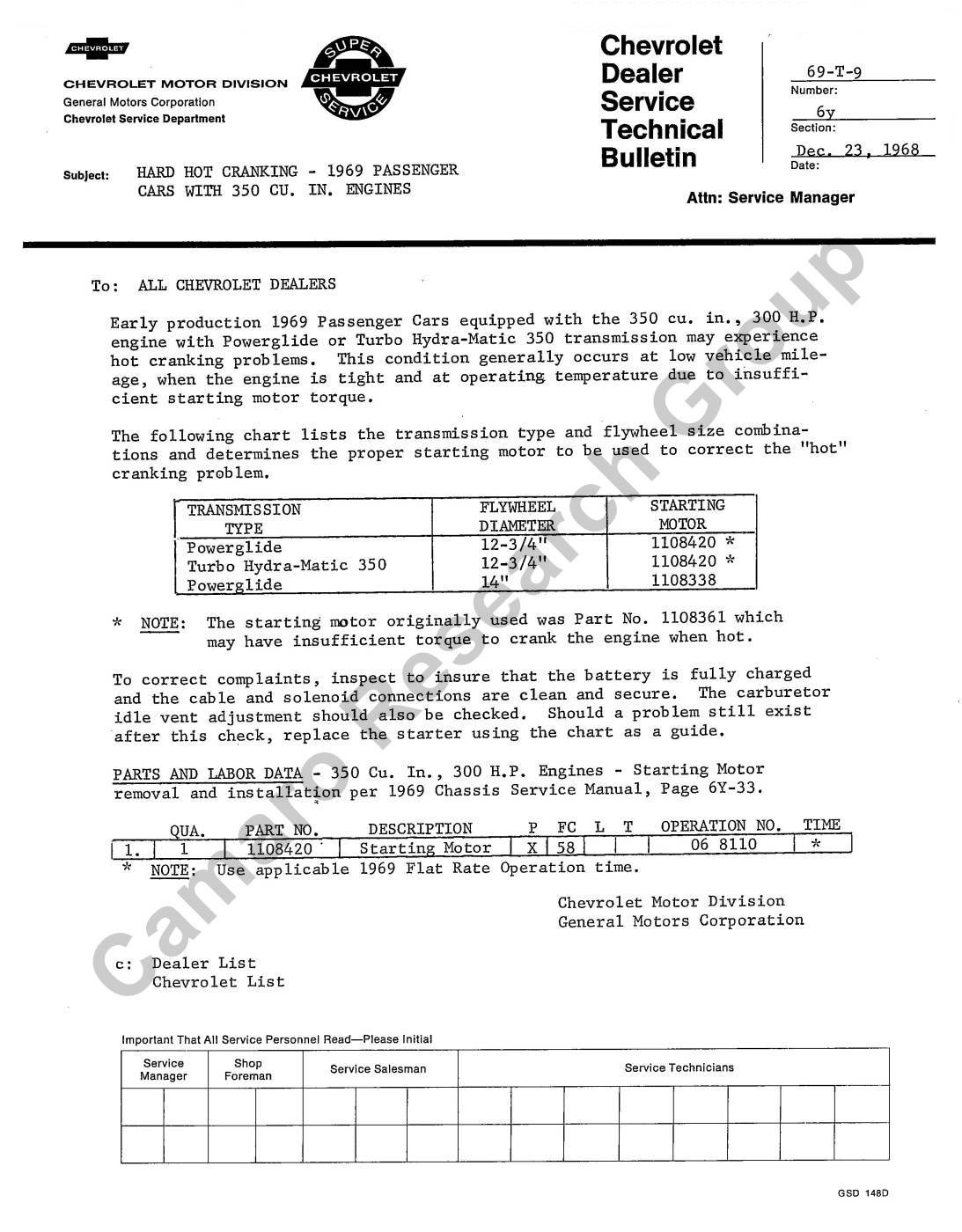
The 69 SS350 with automatic transmission had a hot restart issue. A
TSB was issued with information
about a service fix and a change in the factory starter. The change occurred before November 1968.
The ZL1 with manual transmission used the smaller and lighter (15#) L88 flywheel which
had less inertia and provided better engine response on the track.
|
|
|
||||||||||||||||||||||||||||||||||||||||||||||||||||||||||||||||||||||||||||||||||
|
|


